.webp "CO2 sensor wall mounting")
.webp "CO2 transmitter wall mounting")
.webp "CO2 meter wall mounting")
.webp "CO2 detector wall mounting")
.webp "CO2 controller wall mounting")
.webp "CO2 monitor wall mounting")
EU declaration conformity


CO2 Sensor | Wall mounting | 24 VDC-PoM
Product description
This smart sensor is designed to measure temperature, humidity, CO2, and ambient light. It indicates CO2 levels with green, yellow, and red LEDs, while all measured data is accessible via Modbus RTU. The CO2 sensor element is replaceable.
The device transmits values through three analogue outputs (0-10V default) and Modbus RTU. It enables ventilation control via its ambient light sensor. All settings and the intensity of the LED lights are adjustable through Modbus RTU.
The sensor operates on 24 VDC and offers flexible connection options with either terminal blocks or an RJ45 connector. It is ideal for controlling air quality and CO2 levels in public spaces such as schools, offices, and restaurants.
Additional specifications and description
Which parameters are measured and why is it important?
This room sensor measures CO2, temperature, relative humidity, and ambient light. The ambient light sensor can be used in applications to control the ventilation system based on the occupancy of the room. The dew point is calculated based on the temperature and humidity measurements. All measured values can be accessed via Modbus RTU communication.
Carbon dioxide (CO2) is primarily generated by human respiration and is therefore a reliable indicator of room occupancy and activity level in indoor spaces. The higher the CO2 level, the more fresh air supply is required to maintain good indoor air quality. That is why in many applications, CO2 sensors are used as an indicator for the ventilation requirements. The Sentera room sensors measure CO2 based on the photoacoustic spectroscopy (PAS) sensing technology. The CO2 sensors do not require (re)calibration since the Automatic Baseline Correction (ABC) algorithm is enabled by default.
What are the configuration and customisation options?
The sensor has three analogue outputs. Each of them transmits one of the measured values and the output value changes in proportion to the measured temperature, relative humidity or CO2 concentration. Different output types are available, including 0–10 VDC, 0–20 mA, 0–100% PWM, or Modbus RTU. By default, output 1 provides the measured temperature, output 2 relative humidity, and output 3 carbon dioxide. The output type is set to 0–10 V. Output 1 will transmit 0 V at 0 °C and 10 V at 50 °C.
The sensor offers a clear, visual status indication of one of the measured values via the green, yellow and red LED light. By default, this is set to CO2. The green LED indicates that the CO2 level is within range, which means there is sufficient fresh air supply. Yellow signals the alert range, and red indicates that CO2 levels are too high and/or that there is insufficient fresh air supply. The light intensity of the LEDs used for status indication can be adjusted. Modbus RTU communication is used to transmit the measured values and can be used to change all of the settings. The Modbus register map provides a complete overview of all adjustable settings.
How is the sensor installed, and what are the power and connectivity requirements?
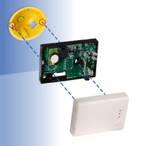
The sensor is intended for mounting on a wall or flat surface indoors. The mounting holes are designed to accommodate standard European wall mounting boxes. Two screws are required to secure the sensor to the wall mounting box. The enclosure fully covers the wall mounting box.
This sensor can be connected using the cage clamp terminal blocks or the RJ45 connector. Via the terminal blocks it is possible to connect the outputs, Modbus RTU communication and the supply voltage. Via the RJ45 connector the supply voltage and Modbus RTU communication can be connected. Never connect the supply voltage via the RJ45 connector and the terminal blocks simultaneously.
The supply voltage is 24 VDC. The ground terminals of the power supply (V-) and output (GND) are not connected internally. This means that a 4-wire cable is required to connect this sensor: two wires for the supply voltage and two wires to connect the output(s). A 24 VDC supply voltage increases the safety and reliability of your installation, by offering protection against short circuit, overload and overvoltage. The cage clamp terminal blocks reduce wiring and installation time. They eliminate the need for routine maintenance and guarantee a reliable contact for solid or stranded wires.
What are the manufacturing quality and protection ratings?
All sensors are designed and manufactured in Europe. Each device is calibrated and tested in our factory. Only high-quality components are used, ensuring long-term stability and accuracy
The enclosure is produced in-house by Sentera Plastics from premium R-ABS plastic, providing exceptional strength and durability. It is designed for indoor use and offers an IP30 protection against ingress of dust and moisture. With its contemporary modern design, the device seamlessly fits into most interior styles. To ensure optimal performance, the sensor should be protected from direct sunlight.


Remarks, reviews & ratings